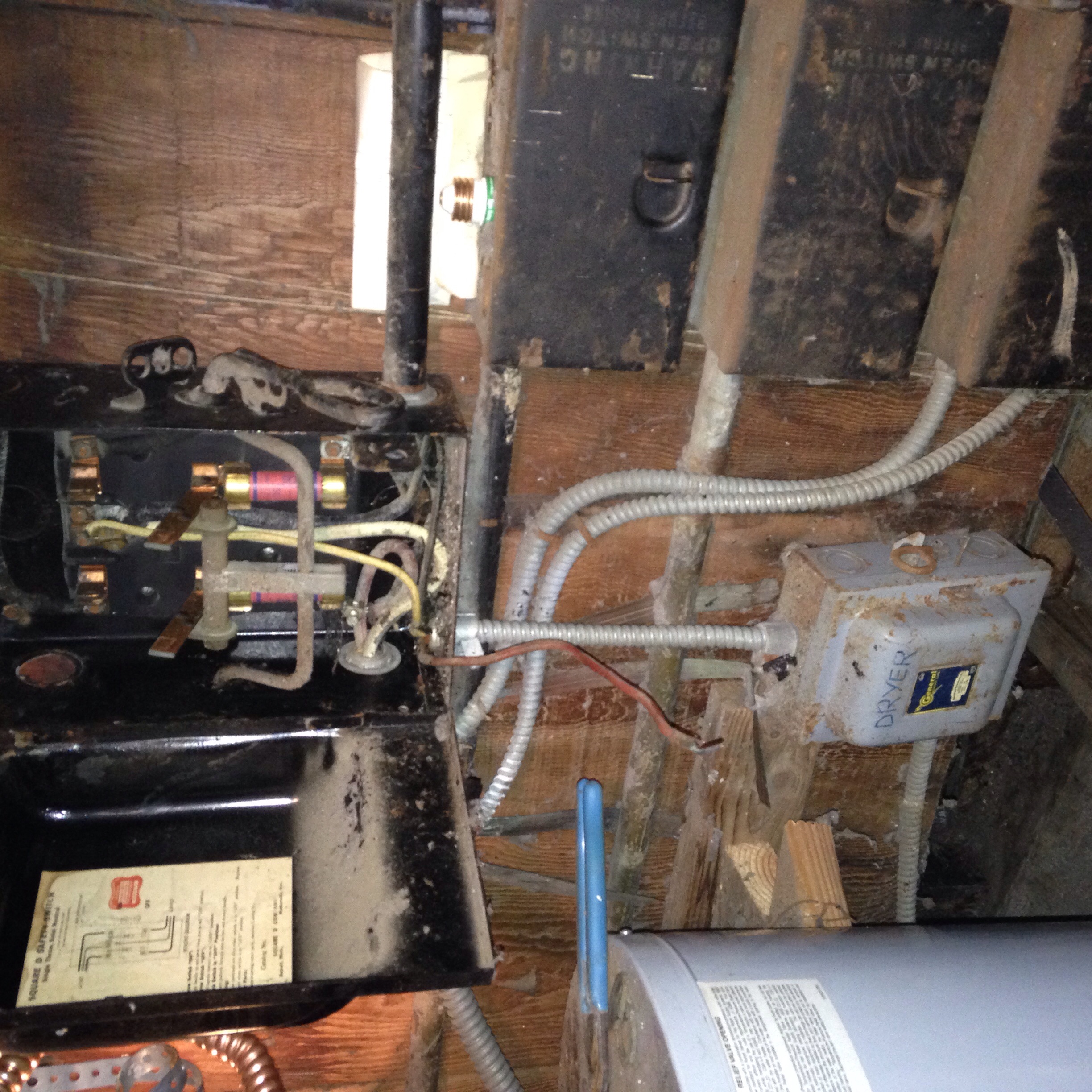
Kitchen Sub Panel Pt.2 - wiring circuits
Starting to pull some wires and wire up the sub panel circuits.
It's good to keep it tidy because there are going to be a lot of wires in there.

Did some rearranging... not written down is I decided to throw the laundry outlet on this sub panel. "C outs is the required 2 countertop circuits" fit into a single space (they sell two 20A (and other amperages) breakers that fit into one typical space). "Disp" is for the under sink outlet used for the in sink disposal.
If you have a dishwasher and a sink disposal, you put two circuits on one outlet! I told you there are a lot of circuits! You get to break these little tabs on the outlet that connect them together. It's a very special experience which is most commonly done for this exact application. Also done for switched outlets used for lamps but that's pretty rare these days. This house has quite a few of them.
If I had room for a dishwasher, I would be averaging one outlet per circuit - I have one counter circuit that has two outlets. Seems crazy but I think the reason for that is the modern American Dream is to have your kitchen remodeled every 10-20 years so the sub panel makes this easy.

This panel is wired
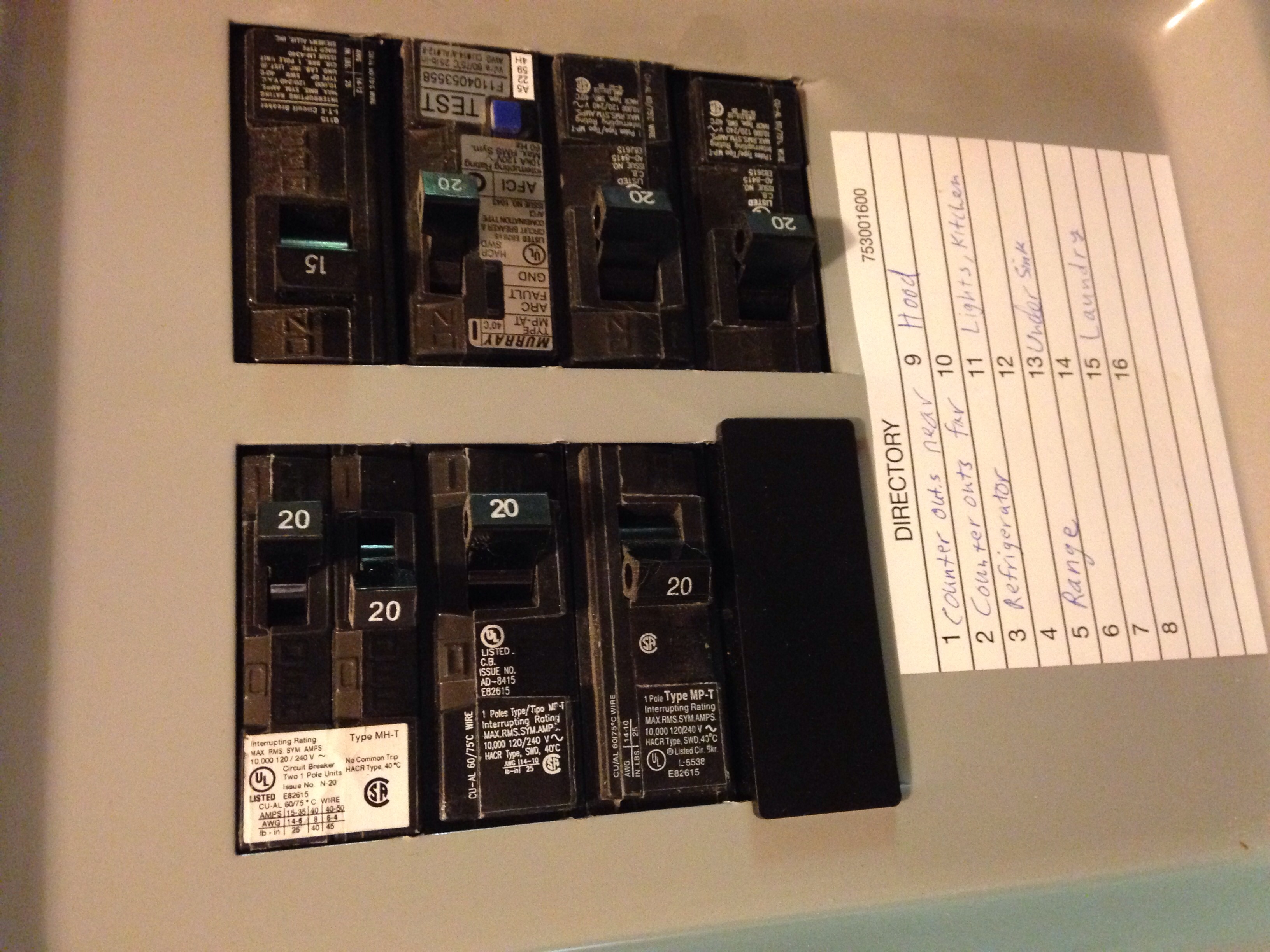
Tested and labeled circuits
Sub panel is done! I double checked each circuit with a beeper before labeling. The black plastic hole cover is only needed if you accidentally break out more grey metal tabs than you need to.